Bosch Motronic - Component Datasheet |
|||||||||||||||||||||
|
Mass Air Flow (MAF) Sensor (G70) –
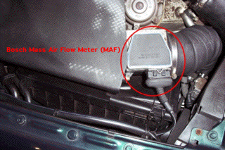
Introduction The air mass sensor, more correctly known as the mass air flow sensor or MAF. It is located in the airbox housing and sits between the air filter and the compressor side of the turbocharger as shown below. It's sole function in life is to measure the amount of air (by mass) entering the engine at any point in time. The MAF device used on the S2 and RS2 is similar to those used on the Bosch LH and Motronic fuel injection system found on many other cars then and today.
The function of the MAF is to provide a voltage signal into the ECU which determines how much air MASS (or weight if you like) is entering the engine. It does this, by passing an electrical current through a thin platinum wire to heat it 100 degrees celsius above the temperature of the air passing over it. This current needs to be larger with increasing airflow in order to overcome the cooling effect of the passing air and maintain a constant temperature on the platinum wire. SideNote - On account
of the heat involved, this type of device is called a 'Hotwire' MAF. I
believe this gives the 'H' notation used in the Bosch LH systems where it was
first employed in the late 1980s by Audi and other German manufacturers. It
was subsequently used on Bosch Motronic systems, and the concept is still
used today in a wide variety of petrol and diesel engined cars. It is an
accurate, cost-effective device that can be used by the ECU to both optimise
performance and emissions. The varying
control current flowing thru the hotwire is passed thru a calibrated
reference resistor network in order to generate a varying voltage at the
output pin on the MAF. This voltage signal is therefore a direct measure of
the VOLUME of air flowing thru the MAF, but we need to know the air MASS. In
order to do this, the density of the air must be known. This is obtained by a
thermistor device (which changes resistance with temperature) that forms part
of the resistor network such that the MAF output voltage is augmented by
temperature effects. A given
volume of cold air is more dense then the same volume of air at high
temperature as long as the pressure is maintained constant. Its also useful
to remember that a constant volume of air at high altitudes (low pressure) is
less dense than the same volume at sea level. These two statements are linked
together by a series of important physical equations known as the ideal gas
laws. This
wiki tells you more on the science fundamentals. Understanding that stuff
will help you understand why turbochargers and intercoolers make engines more
powerful. Of course the ECU has its own means of measuring ambient air
pressure and ambient air temperature by means of F96 and G42 respectively. It
uses these values to make vital adjustments to ignition, fuel and boost
calculations in real-time for the prevailing conditions. |
|||||||||||||||||||||
|
More MAF
Information A honeycomb type screen is placed in at both ends of the MAF housing so as to protect the hotwire filament from erroneous readings caused by air turbulence. This is a small restriction to airflow thru the MAF - you can reduce the pressure drop across it by removing these screens. It is worth noting that the RS2 MAF, whilst electrically identical to the S2 MAF, has much less restrictive baffles fitted. Contamination
of the hotwire will quickly cause inaccurate readings that can result in loss
of performance or foul running. Given the nature of the positive crankcase
ventilation (PCV) system on the S2/RS2 which recirculates oil vapour and
blow-by products thru to the intake system there is potential for this to
collect on the hotwire... Despite the design by Audi to ensure this is
minimised by the fact that these vapours are introduced somewhat 'south' of
the MAF. To ensure it is kept as clean as possible, the hotwire is heated to
a temperature of 1000 degrees C for a one second period each time the engine
is shutdown. This should burn off any potential contaminants. This is all great with the exception that the burnoff sequence actually erodes the platinum hotwire, reducing its accuracy and lifetime. This burn-off signal is triggered by the ECU after the engine is turned off. It is therefore recommended that you wait at least twenty seconds after shutdown before attempting to remove the connector plug from the ECU. Details on how to test the burn-off signal are down here ! Should the
MAF fail entirely (or the electrical connector be disconnected), then the
engine will run in limp home mode such that when the idle throttle switch (F60)
is closed the ECU uses a static ignition map that assumes a certain amount of
air flowing at idle. At part load, when F60 is open, the ignition map is
fixed for 20 degrees BTDC and the mixture is leaned off to get you home. For further
technical information on the Bosch hotwire MAF, there is useful FAQ at this
location provided by JDS
Porsche in |
|||||||||||||||||||||
|
The MAF A common
practice in DIY cleaning of the MAF filament across VW, Audi and other
similarly afflicted owners is to submerge the hotwire filament in a tub
containing a clear liquid chemical known as iso-propyl-alcohol (often
shortened to IPA). It can be obtained at your local pharmacy or from some
electronics / components suppliers. Some people claim wonderful results with
this cleaning as it allegedly dissolves any remnants of the invisible grime
which the burn-off sequence has failed to remove. Others claim no
improvements whatsoever. I believe that the benefits observed from the MAF
Bath are as much to do with the fact that the MAF connector and wiring plug
generally gets a good clean along the way. If you are having
some running troubles, it is worth trying this as it costs almost nothing,
but the test sequences described below are rather more objective. IMPORTANT – Be sure to NOT submerge the part of the MAF with the 6-pin
electrical connector in the cleaning liquid… Just the filament ! |
|||||||||||||||||||||
MAF Part Numbers
Part number
information for the MAF on the S2, and other vehicles, is shown below. The
Porsche 968 application for the RS2 MAF is proof (it it be needed) of the
fastidious component choices by the Engineers from
Ý |
|||||||||||||||||||||
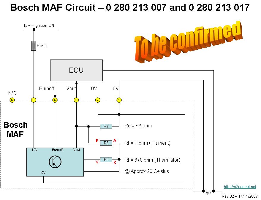
MAF Pinout & Circuit Diagram
The
table below provides the electrical pinout of the MAF device, along with a
description of each pin and where it connects to the ECU on the 3B and ABY
engines. Note this information is also applicable to the RR and AAN/ADU
engines respectively. Strangely, Audi used the same pin numbers on both of
the ECU used for these engines.
The diagram
below depicts the electrical schematic of the MAF and how it connects to the
ECU. The notation of points A, B, X and Y on the diagram below align with the
photographs shown further below and the information on how to quickly test
the MAF quickly and easily.
|
|||||||||||||||||||||
Testing the MAF – Part 1,
External Checks
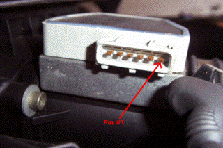
Using a digital multimeter (DMM) the MAF and its wiring can be quickly checked in four steps after removing the connector at the MAF. Pin #1 is the RIGHT-most pin when viewing the MAF from the top and the LEFT-most pin when viewing the harness connector face on.
3.
With the MAF connector removed, and the DMM still set for low resistance
values, verify that 3 ohms is measured between pins #1 (one) and #3 (three).
This is a measure of the internal reference resistor, Ra, shown in the above
schematic. 4.
Connecting the harness plug back onto the MAF, again teasing back the
insulation hood enough to get the DMM probes onto the pins entering the
connector, measure DC VOLTAGE across pins #1 (one) and #3 (three).
NOTE
– When refitting the MAF connector for the final time, it is important
to check the cleanliness of the connector pins and that the insulation hood
is firmly in place to ensure that moisture and dirt do not have an
opportunity to get to the electrical connections. Such defects can give rise
to erroneous MAF readings and some running issues. If I ever
track down a voltage to mass-air-flow graph for the S2 MAF I shall post it
here. An internet search might find you a similar device from a Porsche to
depict the shape of the curve. The maximum output voltage is ~5V of course...
The ECU is aware of the calibration between this voltage value in terms of
'how much air' that corresponds to at any given time - it uses that for fuel,
boost and timing calculations. |
|||||||||||||||||||||
Testing the MAF – Part 2, The
Burn-Off Signal
If the
burn-off signal is not visible within the MAF, then test for the trigger
signal from the ECU at pin #4 (four) on the MAF connector. If the ECU is
providing the burn-off signal and the MAF isn't obeying this command, the MAF
should be replaced as it is not a serviceable component. |
|||||||||||||||||||||
Testing the MAF – Part 3,
Internal Checks – Careful Now
Further tests
to the MAF can be performed if there are potential problems identified by the
Part 1 and Part 2 tests.
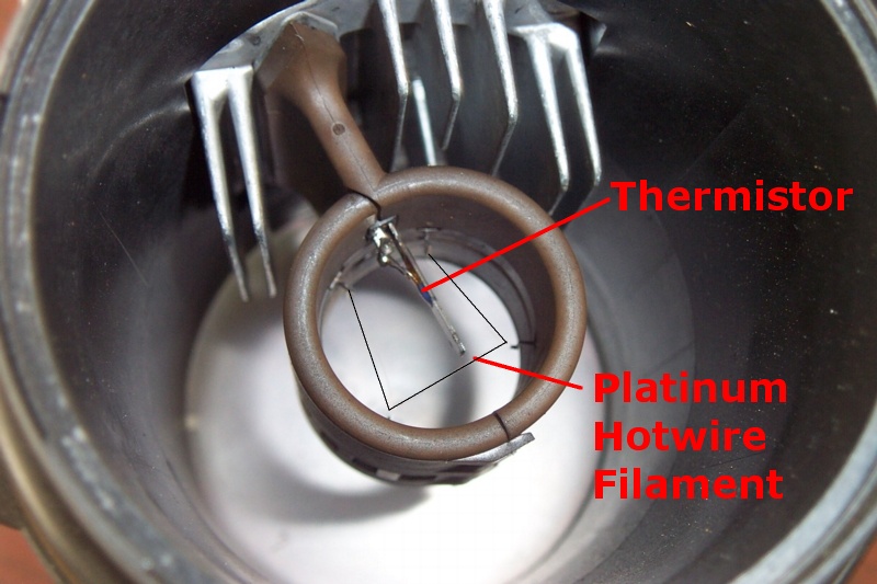
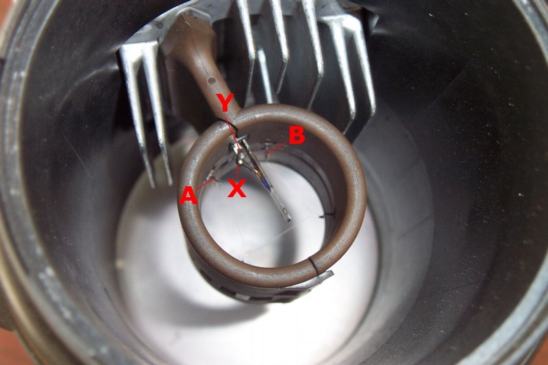
If you have
got this far, the MAF is already detached from the airbox and it is now a
simple matter of removing it entirely and placing it on the bench for some
careful tests with that multimeter. The image above shows the internals of
the MAF, viewed from the airbox side of the housing. I have highlighted the
hotwire filament in this image for clarity. In order to get this far of
course, one has to remove the retaining ring and metal honeycomb mesh at the
airbox end of the MAF housing. In order to
align with the schematic shown above, I have added the labels A and B for the
hotwire filament and labels X and Y for the thermistor.
With great
care, using the DMM set to low resistance values, it is possible to check the
following –
Resistance
across the hotwire filament (Rf) should be approx 1 ohm (pins A and B)
Resistance
across the thermistor (Rt) should be approx 370 ohm (pins X and Y) at 20
celsius
Pins A and X
should be a short circuit (0 ohm)
Resistance
between MAF connector Pin #3 and pin B should also be 0 ohm
Resistance
between MAF connector Pin #1 and Pin Y should be Rf + Rt + 3 ohms Please note
that these resistance measurements should be considered as a reasonable
guideline for what to expect when testing the MAF – they are not
absolute and the value of Rt shall alter noticeably with temperature. This
thermistor is a PTC device and will yield lower resistance values at lower
temperatures. The DMM I have used is not the most accurate thing in the
world. As a final
behavioural check on the MAF, with it connected to the wiring loom, any
screens refitted and the ignition on - you can use one of those hair dryers
that has the ability to blow at multiple speeds with a couple of heat
settings. You should see lowest MAF output voltage with the slowest/hottest
setting on the hair dryer and the highest voltage output with the
fastest/coldest setting. Use some common sense here so as not to blast hot
air directly onto the filament. |
|||||||||||||||||||||
Testing the MAF – Part 4,
More Tests & Calibration Information
Further tests
to the MAF, to verify its calibration, require an accurate flowbench and
industrial test & measurement equipment against a known fresh and healthy
reference MAF. One specialist company in the Bosch are
notorious for being protective about component information. As such, it is
impossible to find a graph of output voltage against input air mass for the
S2 / RS2 MAF. However, I am in the process of working out a way to reverse
engineer this information with the help of an entirely different MAF (that
does have published data) and the assistance of the flowbench at JDS. Watch
this space for an update on that. It may not be
deadly accurate, but by the wonders of applied mathematics, that work shall
provide a means to estimate engine power by simply measuring the output
voltage of the MAF. If I find a field on the diagnostic channels within the
ECU that directly reports MAF voltage, then it will be possible to log this
information with VAG-COM. No promises here – it is work in progress
shall we say. |

Last Updated 23rd November 2007