|
Introduction to S2
Wiring These pages provide some of the
schematic information on the S2. This stuff isn't easy to get hold of, and there
are some missing sections - particularly on the ABY engined S2 but I will
annotate the almost identical ADU information as best I can to provide an
initial view on the ABY schematics. You will note
that the source of the 3B Schematic is Norwegian, so I have provided the raw
Norwegian and English annotated versions on the respective pages. The colour
scheme on all the wiring diagrams is identical (thank goodness) as it is derived
from the original German scheme which is listed below.
| Code |
Colour |
| bl |
BLUE |
| br |
BROWN |
| ge |
YELLOW |
| gn |
GREEN |
| gr |
GREY |
| li |
PINK |
| ro |
RED |
| sw |
BLACK |
| ws |
WHITE |
Other things to note when trying to understand the
wonders of S2 wiring diagrams are that there are three locations for relays.
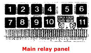
- The main relay (and fuse) carrier located under the
bonnet near the corner of the bulkhead on the drivers side
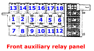
- The front auxiliary relay carrier is located below the
dashboard, just above the drivers pedals
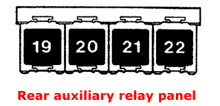
- The rear auxiliary relay carrier is located below the
rear seat
|
Furthermore, the numbering scheme for all of these relays does not
rely on the traditional methodology and common sense that you would normally
associate with our favourite German car manufacturer.
Its all a bit confusing at first, but here's a few simple
pointers to sort out any potential confusion. The relays in the main panel are
numbered 1 to 11. The relays in the front auxiliary panel are numbered 1 to
18 whilst the relays in the rear auxiliary panel are numbered 19 to 22. Each
panel is shown in the associated figures. So there are actually two sets of relays numbered
1-11 which is insane...
The nomenclature that I use is M1-M11 for relays in the
main panel and A1-A22 for the auxiliary relay locations. This avoids the
confusion on relay positions 1 through 11.
However, the S2 schematics do not have any
special numbering to sort out the mess. The method used on the factory S2
schematics to differentiate relay positions 1 thru 11 from the main and
front auxiliary relay panel is quite simple though - If
the relay appears in the top section of the schematic like
this, then
the location is the main fusebox. However if the relay is drawn outside
of the top section, like
that, then the location is an auxiliary panel.
|
|
|
|
|
|
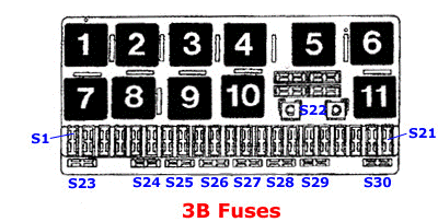
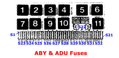
| There is similar confusion with respect to some of the
fuse locations on the S2 wiring schematics. As far as the schematics are
concerned, fuses at locations of S23 and above are located in the
'auxiliary fuse panel', but they are in fact located in the main fusebox
with the rest of the fuses in the vast majority of cases. This applies
to fuses S23-S30 in the 3B Coupe and to fuses S23-S32 in the ABY cars.
It is doubly confusing because the fuse numbering scheme changed for the
ABY motors such that the two spare fuse positions in the 3B fusebox are
deleted on the ABY and the numbering was changed accordingly.
Still confused - The figure on the left shows the fuse numbering on
the 3B and the figure on the right shows it for the ABY (and ADU). |
|
|
|
By the way - Fuse S22 is only used on diesel engined
varieties of the Audi 80/90 series... And while we are talking about fuses, many
S2 owners will have noticed the little red two-fuse-carrier labeled 'Motronic'
that resides in the fusebox. On the 3B, this couples fuses S26 and S27 (for the
lambda sensor heater and ECU) whilst on the ABY, it couples fuses S27 and S28
(for the ECU, fuel injectors and MAF). Now where's the sense in that ? Click
here for more details on the S2 Motronic schematics.
|


